 返回
返回顶部
MyEclipse provides the following UML 1 features:
Note: The contents of this document refer to the UML1-based feature set in MyEclipse. Please note that there are both UML1 (![]() ) and UML2 (
) and UML2 (![]() ) tooling available in the IDE. Similar documentation of the UML2 features are available in the UML2 overview.
) tooling available in the IDE. Similar documentation of the UML2 features are available in the UML2 overview.
The MyEclipse UML perspective provides a workbench organization tailored to activities of the modeling process. Default views include the UML Diagram editor, Outline view, and custom Properties view. Toolbar actions are added to make new diagram creation quick and simple. When you create a new UML model in a project, you are prompted to open the UML perspective.
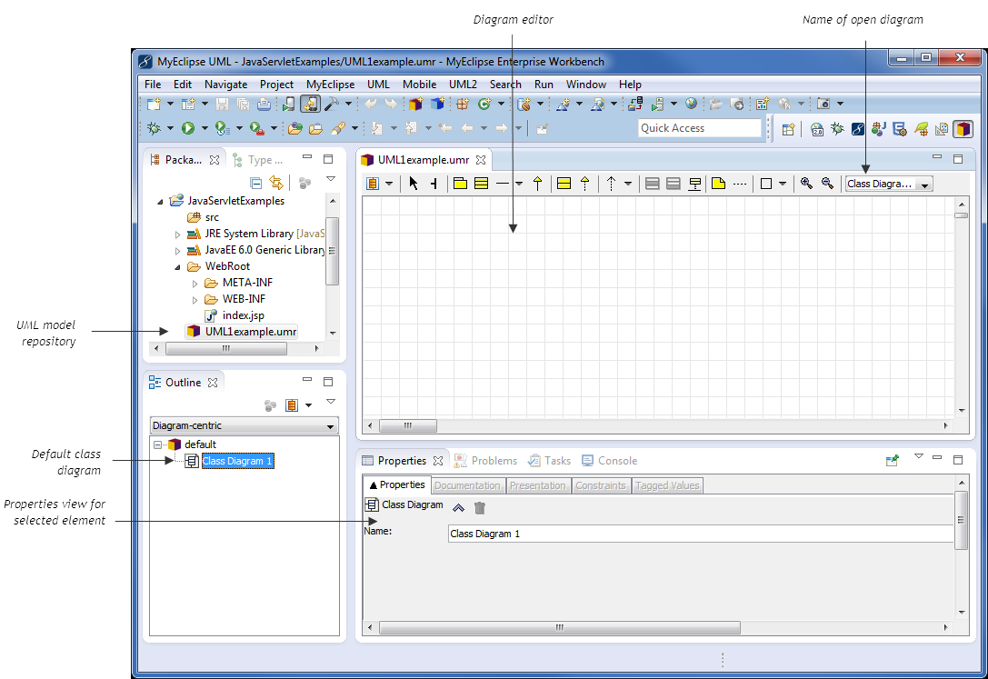
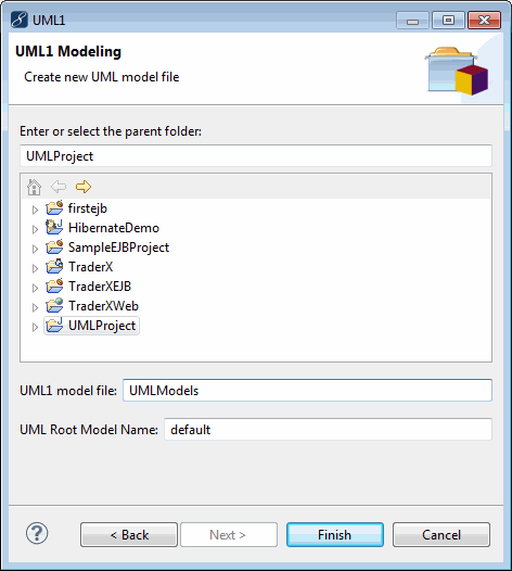
Getting started with MyEclipse UML begins with the creation of a UML Model Repository file (UMR). After creating the new UMR file, you are taken to the MyEclipse UML perspective.
The MyEclipse UML perspective provides many specialized tools for developing and working with UML diagrams, including:
Support for seven of the most popular kinds of UML diagrams
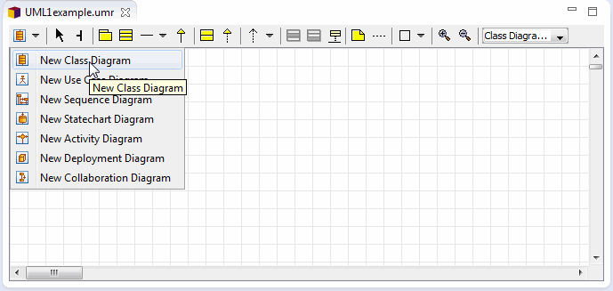
Easy management of multiple diagrams in the same UMR file

Diagram-specific tool bars that allow you to create and modify your diagrams quickly and easily


Support for inline editing of elements directly in the diagram

Quick-connect support for elements that support relationships with other elements in a diagram
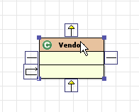
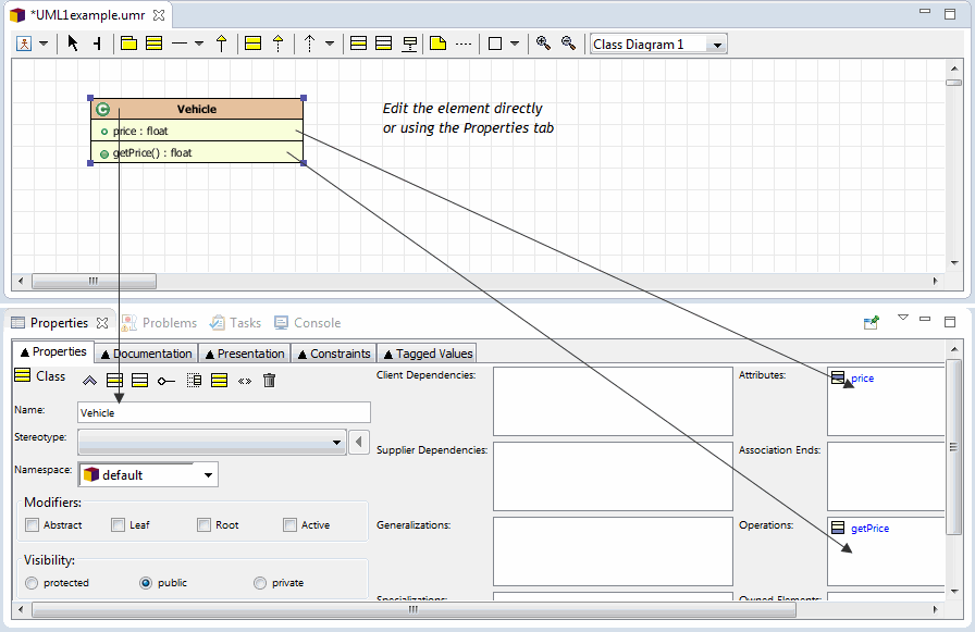
Context-sensitive properties for the elements you are working with directly in your diagram
There are many more tools available to you as a UML developer like exporting your diagram to an image so it can be included in documentation, printing or even auto-laying out the contents of the diagram using an advanced layout algorithm.
The MyEclipse UML tools are geared towards an Agile development model, helping you to get up and running quickly either reverse-engineering a project into diagrams to better understand it, or generate source code from a diagram to get started quickly.
One of the most powerful features of the MyEclipse UML tool set is the ability to forward and reverse engineer code to and from your diagrams. Forward engineering can be accessed when a Class Diagram is being viewed from the UML menu
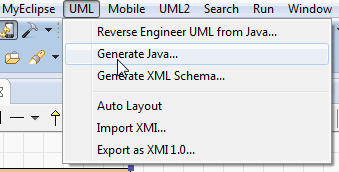
During the forward engineering step, you can select the classes you want read out of your project and convert them into a class diagram using the wizard.
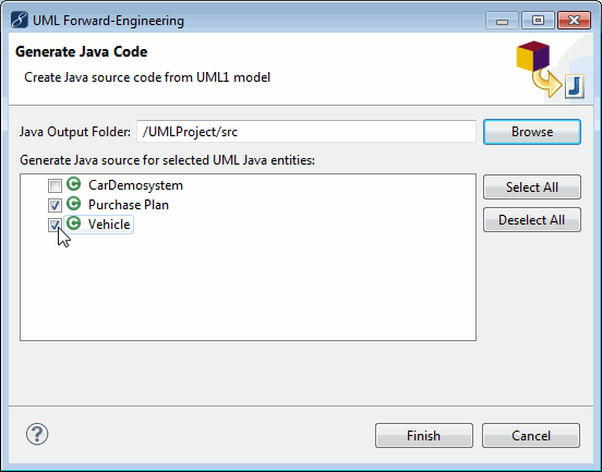
The forward engineering step generates not only the classes and interfaces described in your diagram, but also any relationships (e.g. inheritance) specified.
In addition to forward engineering, the MyEclipse UML tools also supports reverse engineering, or the ability to read source code out of your project and generate class diagrams from them. This can be helpful when analyzing a new or complex source tree and trying to get a better understanding of how all the parts interact. The reverse engineering process can also be helpful for generating diagrams for documentation purposes.
Reverse engineering can be initiated two ways, one from the UML menu, just as the forward engineering step, and the other way is using drag and drop.
Using drag and drop reverse engineering is the easiest mode. You select the classes you want from your package explorer and drop them directly into your diagram. The new diagram is created for you instantly.
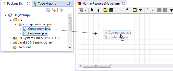
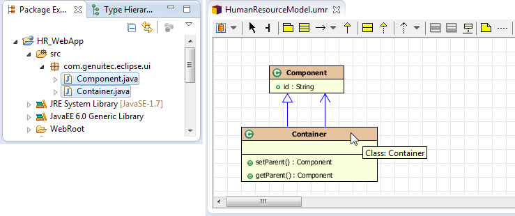
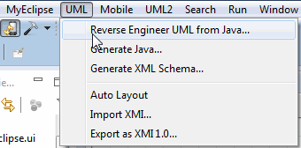
To access reverse engineering from the menu, select UML>Reverse Engineer UML from Java menu item.
Select the elements from your project’s source that you want included in the diagram.
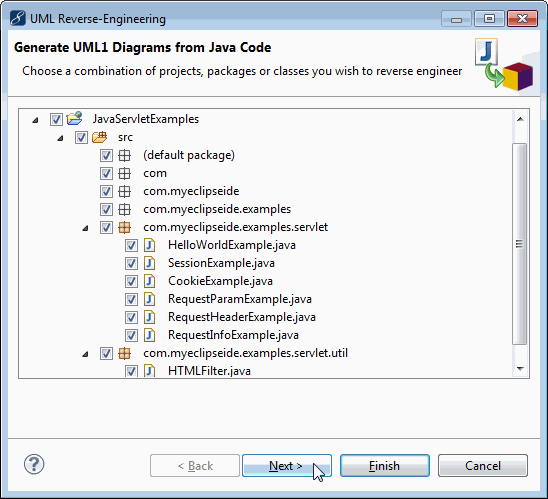
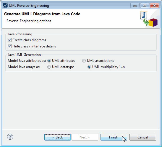
Fine-tune the reverse engineering process before continuing.
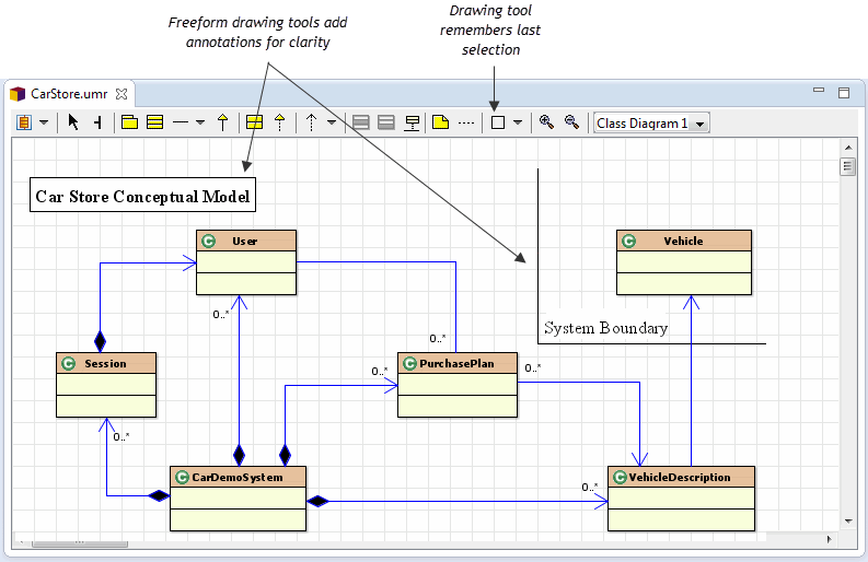
Many diagram tools are limited when it comes to usefully describe the diagram to another developer or manager; this is especially true when you are limited by the diagramming tool’s ability to annotate or decorate your diagram with notes or prompts.
The MyEclipse UML tool supports generic drawing tools for the different types of diagrams.
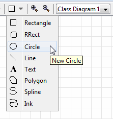
These free-form drawing tools allow you to annotate any diagram in any fashion you like without effecting the actual layout or meaning of your diagram.
